

Creating a stylized grass shader using Unity Shader Graph. (Part-1)
Search for a command to run...
Who has the source code of a mature and large-scale multiplayer online mobile game from a major game company? It is required that there should be mature commercialization and in-app purchases in the game, such as: card drawing, opening boxes, etc. We are in Vietnam and I am willing to pay super high fees to buy. Contact me q791864008q@gmail.com
In this series, I breakdown shaders I've created, in a step by step process.
In the previous part, we made a customizable stylized grass shader. In this part, we'll be adding animation to create the wind effect. Introduction The way we are trying to achieve wind effect will be split into two methods. The first method will be ...
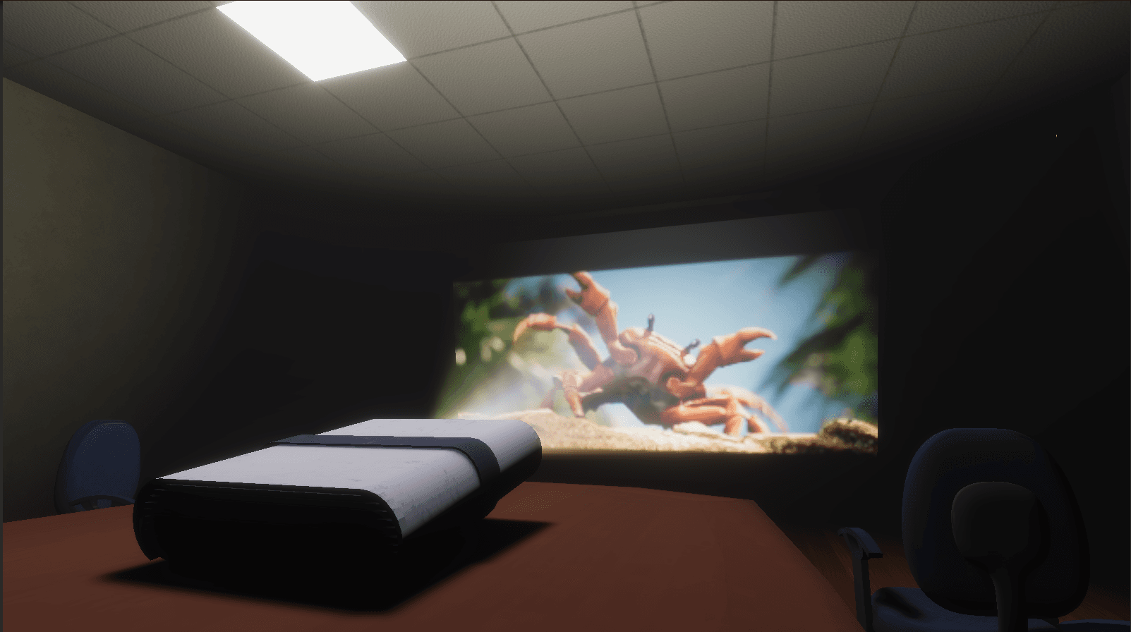
Hey there! Let me tell you about a simple way to create a video projector in Unity, The idea is to let us play any video of our liking inside Unity as if it's being projected onto a screen. NOTE: This method is intended to work with HDRP and might al...
In the previous part, we made a customizable stylized grass shader. In this part, we'll be adding animation to create the wind effect. Introduction The way we are trying to achieve wind effect will be split into two methods. The first method will be ...
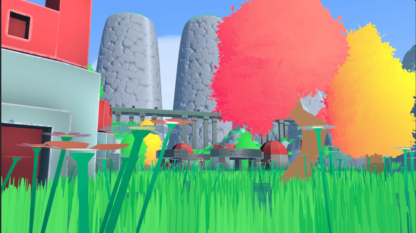
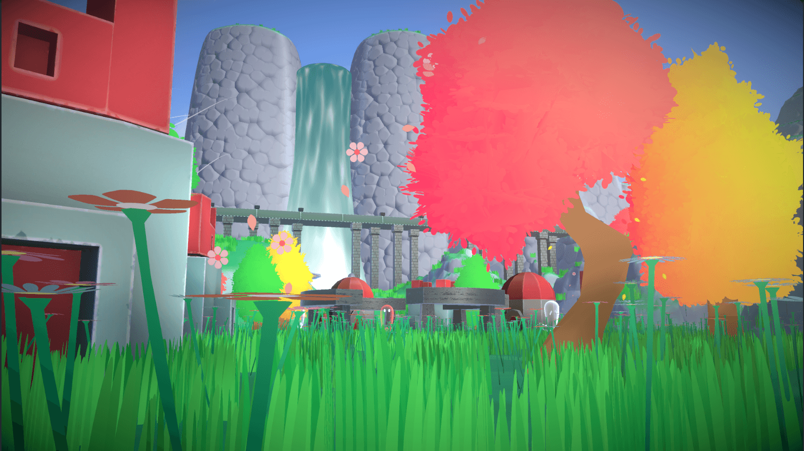
Hello everyone, This is a breakdown of the stylized grass shader I made for our game Trials For Paradise.
When we started developing the game we wanted it to have a stylized art style, So I started looking around the web for inspiration. Soon into my research, I found tutorials and articles about grass shaders (I'll link them down below), which were helpful, but I felt it was not satisfying our needs, Then I came across an article from 80 level - Unity Shaders for Stylized Scenes by Jonathan Van Immerzeel, The method he used was interesting. His shader was customisable such that the grass's properties can be modified, I liked the customizability it would provide to our designers to modify it according to their needs. Since Jonathan used Substance Designer to make his grass shader, I wanted to try to recreate it in Unity Shader Graph.
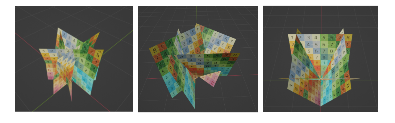
To start, we need to have a mesh to apply the shader. I had multiple ideas on how to create the mesh, should we make a single blade of grass? or create a model of grass? both of which might have more polys, Since we wanted our game to have better performance I opted to use only a quad and we get to add as many blades of grass as we want using the shader anyway, so in Blender, I created a mesh which was just 4 quads merged at the centre. As we can see I made the UV such that it aligns in a vertical orientation which will be useful when we add the shader.
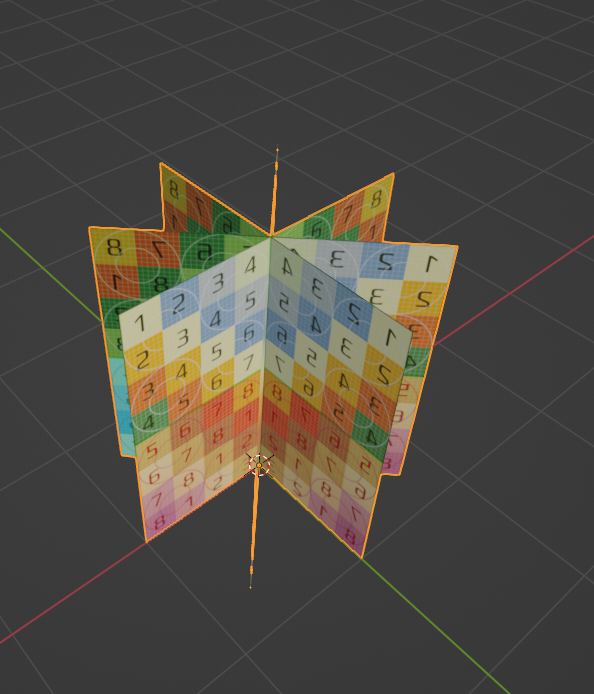
The problem with this mesh is that if we see it from the top, the mesh disappears. This isn't a big deal for a game in a third-person perspective, so your mileage may vary, just to try to overcome this problem, I did create some variations, but I did not like how they looked in our game, so I went with the original one.
Note: Make sure the pivot point/anchor is at the bottom of the mesh, this is useful if we want to paint the mesh in the terrain
To start, Let's create an Unlit Shader Graph, opening it up we can see two sections called Vertex and Fragment.
In brief:
The Vertex shader is used to affect the vertices of the 3D object.
The Fragment shader is used to affect how they look on the screen (the colours, the texture etc.).
For now, let's focus on the Fragment shader.
Before we start making the shader there are some Graph Settings we need to take care of.
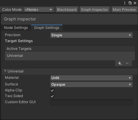
The first is "Alpha Clip" this is useful if we wanted to clip based on the alpha.
The second is "Two Sided", since the mesh is viewable from all angles and each quad is a single face we have to enable it to make it visible on both sides.
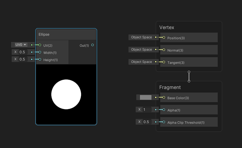
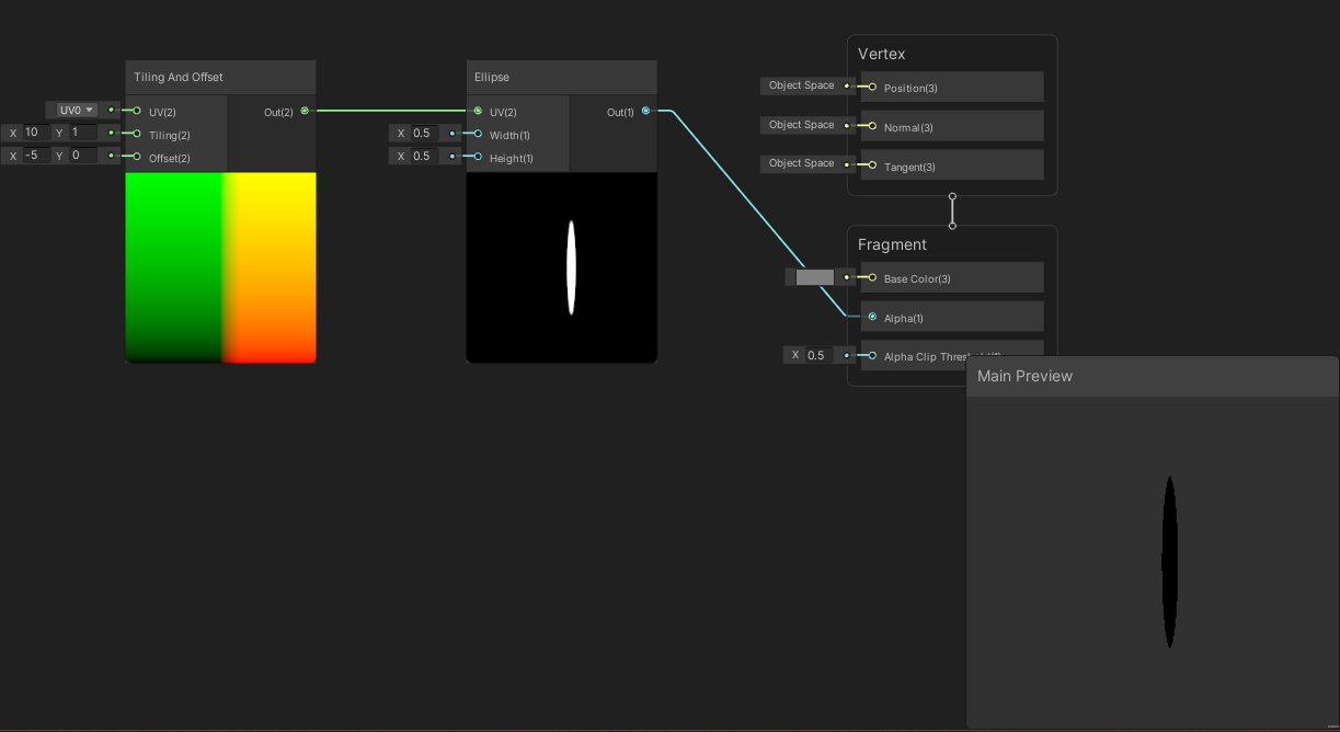
Let's create an Ellipse node by right-clicking in the shader graph and selecting "Create Node" or by hitting the Space bar, we can use the search to find the exact node.
Let's see what happens if we connect the Ellipse Output node to the Alpha node of the Fragment shader.
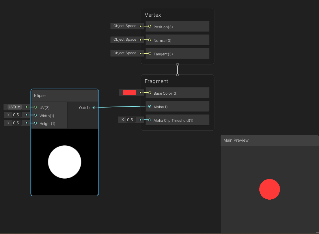
We can see that the colour is only visible where the ellipse is.
Notes:
The alpha node works by showing only the areas where it's white which means it's opaque, and will not show areas where it's black which means it's transparent, it will also vary the opacity as per the shade of grey.
Here is where the Graph Settings come to be used since we enabled Alpha Clip we can use the Alpha node.
If you can't see the preview flat like mine, right-click in Main Preview and select "Quad".
Add a Tilling and Offset node and connect its output to Elipse's UV input. Try playing with the Tilling and Offset Input parameters and see the results.
We can see this is starting to look like a blade of grass however if we try to increase the tilling we can only see one shape, to get multiple copies we need to add a Fraction node between Tilling and Offset & Ellipse nodes.
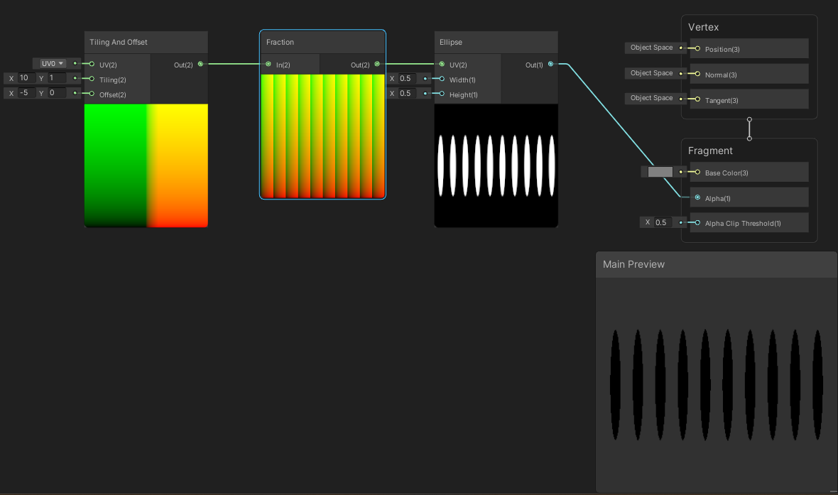
There we go, it's looking like many blades of grass.
Before we move further let's add some properties to modify the parameters later when we create our material.
For the tilling and offset we'll add a Vector 2 property, call them "Grass Tilling" and "Grass Offset", and to control the ellipse's width and height let's add a Float property, call them "Grass Width" and "Grass Height"
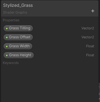
Drag and drop them in the shader graph and connect them to their respective inputs.
Click on each of them and in the Node Settings tab under the Graph Inspector let's give them a default value so we could see how it looks in the preview.
Default values I used:
Grass Tilling: X=11, Y=1
Grass Offset: X=1, Y=0.18
Grass Width: X=0.5
Grass Tilling: X=0.6
We got the grass but all the blades are too perfectly the same right? Let's add some variations to the height.
Disconnect the link between Tilling and Offset node and the Fraction node by clicking on the link and deleting it.
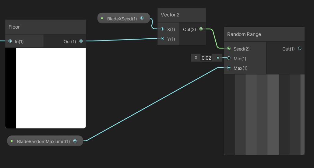
Add a node called Split, this node splits a vector 4 input into individual outputs. Connect the Tilling and Offset's output to the input of the Split. Then add a node called Floor, this is a math node which rounds the value. Take the "R" channel output of the Split node and connect it to the input of the Floor node**.**
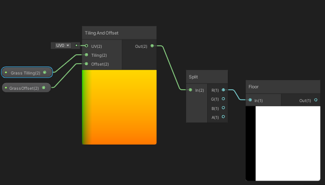
What we have done is take only the X value of Tilling and Offset and round them off to an integer, this is done to offset each tile separately and non-uniformly.
Add a node called Random Range, which is used to create random values based on a given Seed value (Vector 2), Create a Float property called "BladeXSeed" and combine it and the Floor output to a new Vector 2 node, connect its output to the seed input of Random Range.
Create and connect a Float property to control the Max value of the Random Range called "BladeRandomMaxLimit", I have kept a default value of 0.02 for the Min value, but we can add another property if we want more control.
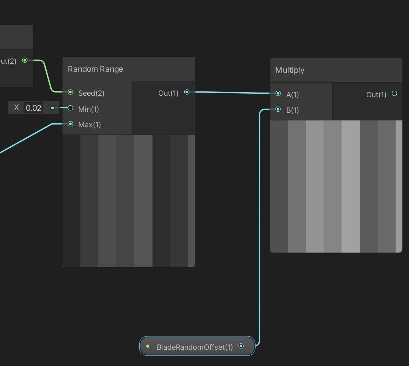
Up until now, we have created a way to offset each tile separately based on a random value. Let's amplify the offset value by multiplying it with a Float property called "BladeRandomOffset".
The hard part is done! we just have to add it with the original Tilling and Offset output but if we recall, in the beginning, we took the "R" value which is the "X" component of Vector 4 (R, G, B, A --> X, Y, Z, W) but, we are offsetting it for the Y component, so let's add it to Y input of a new Vector 2 node and keep X input 0, now we can add the values by using the math node Add.
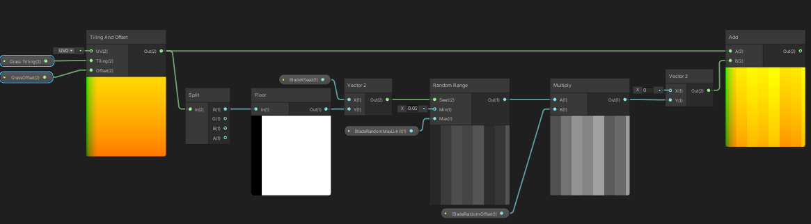
Connect the output back to the Fraction node we created at the beginning, and see the magic!
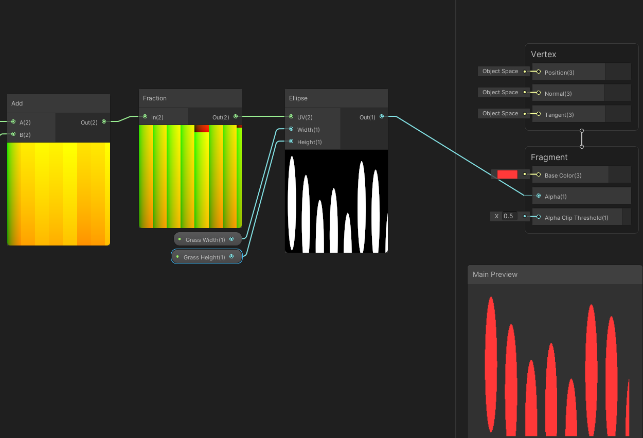
We can see, we have created random heights for the grass! Play around with the properties and see the variations.
Note: We might see the grass clipping at the top if we adjust the properties and also clipping on either end for certain values, this is where this shader lacks. so try to adjust the values further to mitigate the issue.
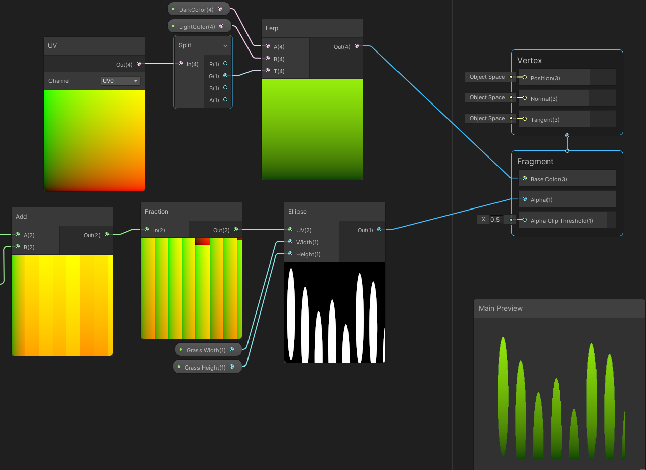
We also need to add colour to the grass, let's do a simple gradient.
Create a UV node and connect it to a new Split node, Create a new node called the Lerp node, which takes two values "A" and "B" and mixes them based on a third value called "T", Take the "G" output of the Split node and connect to the "T" input of the Lerp node, create two Color properties called "DarkColor" and "LightColor" connect the "DarkColor" to the "A" input and "LightColor" to the "B" input of the Lerp node. Finally, connect the output of the Lerp node to the base colour in the Fragment shader.
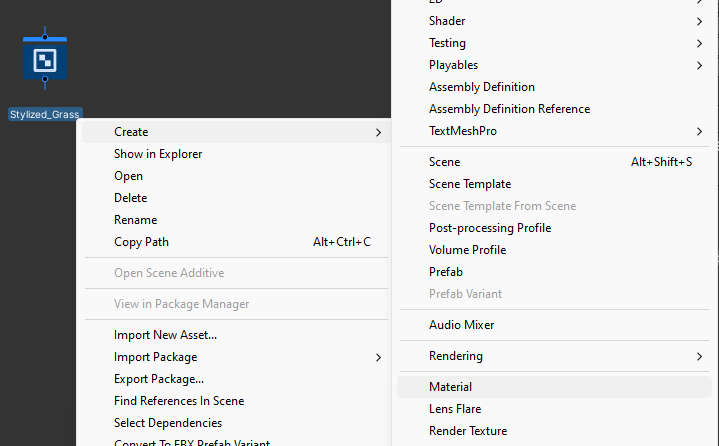
Alright, we have finished the base shader. Let's make a material using this shader graph.
Once we are done making the shader, let's make a material using it and apply it to the mesh we have created. Right-click on the shader graph and go into Create and select Material.
Apply it to the mesh and see how it looks.
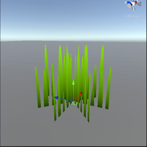
There we go, We can customise the grass properties to suit our needs.
In the coming parts, we'll see how we can add animations to create the illusion of wind, lighting and colouring differently and add layers of grass to make it more lively.
Let me know if you like it or not and if you have any feedback, Thanks for reading!
I used Unity Version 2020.3.33f1 and Shader Graph Version 10.8.1.
I used URP version 10.8.1 for our game, but it is possible to recreate the shader in HDRP.
References: